2023.10.08.(일)
Digital Transmission: Digital-to-Digital Conversion
- Data can be either digital or analog.
- Signals that represent data can also be digital or analog.
How can we represent digital data by using digital signals?
The conversion involves three techniques
- Line coding
- Block coding
- Scrambling
Line Coding
Line Coding
- The process of converting digital data to digital signals.
- Line coding converts a sequence of bits to a digital signal.
- Data, in the form of text, numbers, graphical images, audio, or video, are store in computer memory as sequences of bits
- At the sender, digital data are encoded into a digital signal; at the receiver, the digital data are recreated by decoding the digital signal.
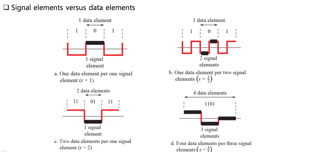
Signal Element Versus Data Element
- A signal element carries data elements
- Data element: the smallest entity that can represent a piece of information; this is the bit
- Signal element: the shortest unit (timewise) of a digital signal
- Define a ratio r which is the number of data elements carried by each single element
- The extra signal element is needed to guarantee synchronization.
Data Rate Versus Signal Rate
- Data rate
- The number of data elements (bits) sent in 1s.
- The unit is bits per second (bps)
- Signal rate (or baud rate)
- The number of signal elements sent in 1s.
- The unit is the baud.
- Relationship between data rate (N) and signal rate (S)
S = N/r
Bandwidth
- Bandwidth of a nonperiodic signal is continuous with an infinite range
- Although the actual bandwidth of a digital signal is infinite, the effective bandwidth is finite
- The baud rate, not the bit rate, determines the required bandwidth for a digital signal
Baseline Wandering
- Baseline: a running average of the received signal power
- A long string of 0s or 1s can cause a drift in the baseline (baseline wandering) and make it difficult for the receiver to decode correctly.
DC Components
- Frequencies around zero, called DC (direct-current) components, present problems for a system that cannot pass low frequencies
- E.g., a telephone line cannot pass frequencies below 200 Hz
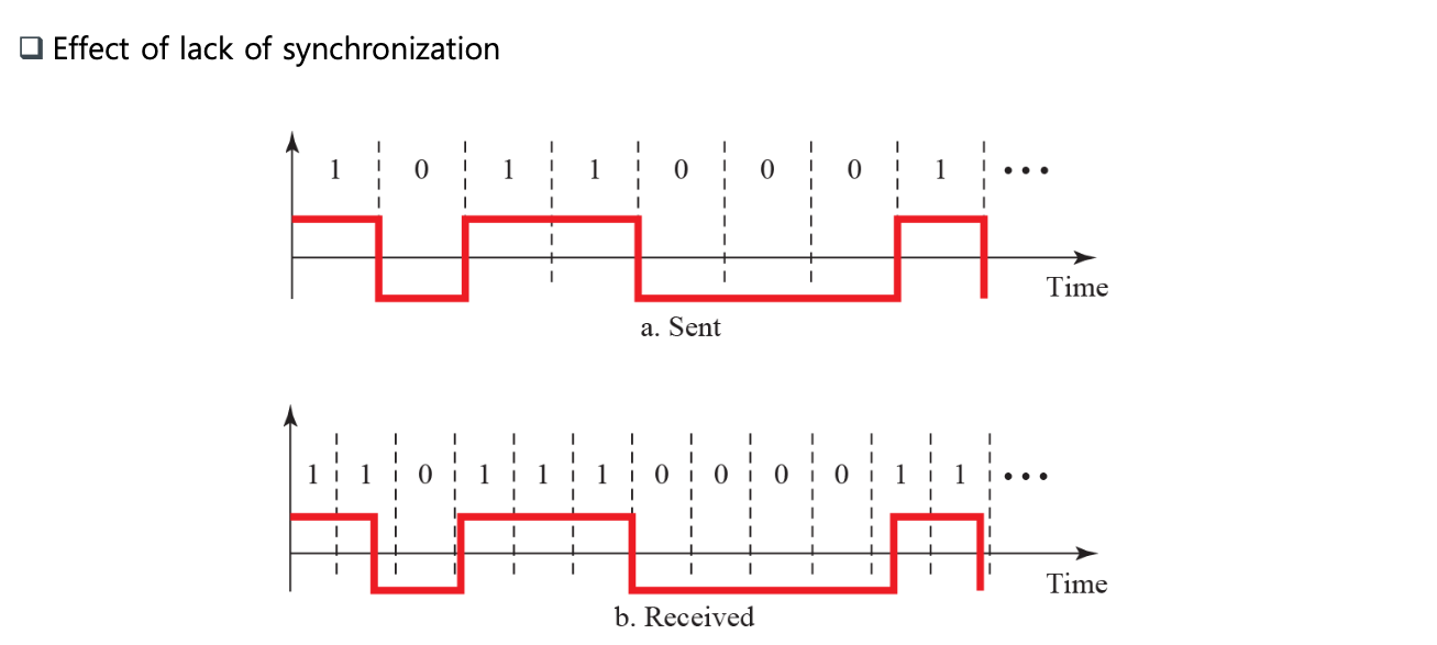
Self-synchronization
- To correctly interpre the signals received from the sender, the receiver’s bit intervals must correspond exactly to the sender’s bit intervals
- A self-synchronizing digital signal includes timing information in the data being transmitted
Built-in Error Detection
- Built-in error-detecting capability in the generated code to detect some or all of the errors that occurred during transmission.
Immunity to Noise and Interference
- Immune to noise and other interferences.
Complexity
- A complex scheme is more costly to implement than a simple one
Rougly divide line coding schemes into five board categories, as shown like
- Unipolar - NRZ
- Polar - NRZ, RZ, and biphase (Manchester, and differential Manchester)
- Bipolar - AMI and pseudoternary
- Multilevel - 2B/1Q, 8B/6T, and 4D-PAM5
- Multitransition - MLT-3
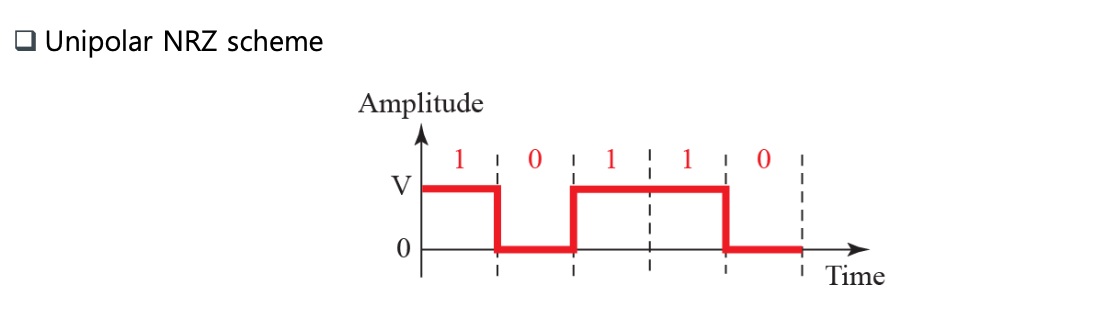
Unipolar Scheme
- All the signal levels are on one side of the time axis, either above or below
Unipolar Scheme: NRZ (Non-Return-to-Zero)
- Signal does not return to zero at the middle of the bit.
Polar Schemes
- Voltages are on both sides of the time axis.
Polar Schemes: Non-Return-to-Zero (NRZ)
- NRZ-L (NRZ-Level) and NRZ-I (NRZ-Invert)
- In NRZ-L, the level of the voltage determines the value of the bit. In NRZ-I, the inversion or the lack of inversion determines the value of the bit.
- NRZ-L and NRZ-I both have a DC component problem.
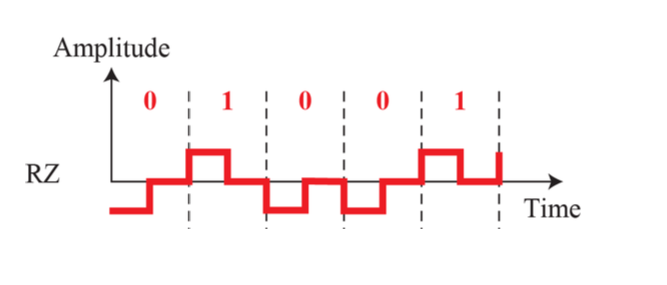
Return-to-Zero (RZ)
- The main problem with NRZ encoding occurs when the sender anad receiver clocks are not synchronized.
- The receiver does not know when one bit has ended and the next bit is starting
- One solution is the return-to-zero (RZ) scheme, which uses three values: po sitive, negative, and zero.
- In RZ, the signal changes not between bits but during the bit.
- No DC component problem
- Disadvantages
- RZ uses three levels of voltage, which is more complex to create and discern.
- Not used today.
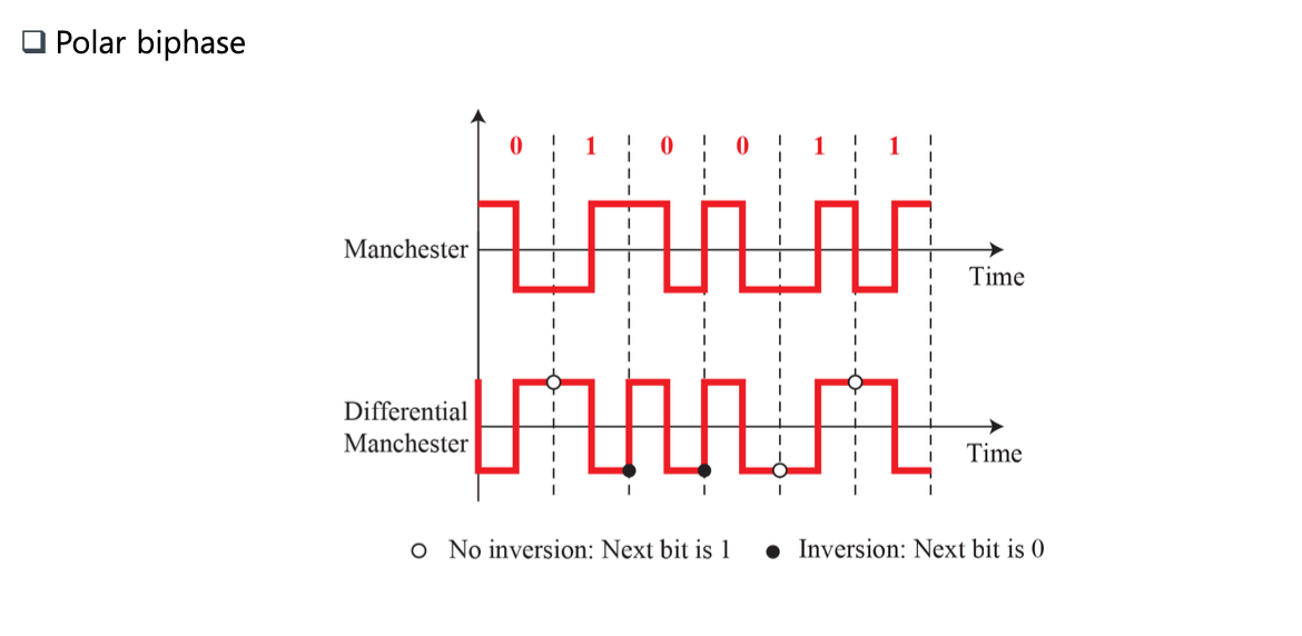
Biphase: Manchester and Differential Manchester
- The idea of RZ (transition at the middle of the bit) and the idea of NRZ-L are combined into the Manchester scheme
- Manchester
- The voltage remains at one level during the first half and moves to the other level in the second half.
- The transition at the middle of the bit provides synchronization.
-
Differential Manchester
- Always a transition at the middle of the bit, but the bit values are determined at the beginning of the bit.
- If the next bit is 0, there is a transition;
- If the next bit is 1, there is none
- Always a transition at the middle of the bit, but the bit values are determined at the beginning of the bit.
- No baseline wandering, no DC component
- Drawback: signal rate
- The minimum bandwidth of Manchester and differential Manchester is 2 times that of NRZ.
- In Manchester and differential Manchester encoding, the transition at the middle of the bit is used for synchronization
Bipolar Schemes
- In bipolar encoding (sometimes called multilevel binary), we use three levels: positive, zero, and negative.
Bipolar Schemes: AMI and Pseudoternary
-
Alternate mark inversion (AMI)
- Alternate 1 inversion.
- A neutral zero voltage represents binary 0.
- Binary 1s are represented by alternating positive and negative voltages
-
Pseudoternary
- A variation of AMI encoding.
- The 1 bit is encoded as a zero voltage
- The 0 bit is encoded as alternating positive and negative voltages.
-
No DC component
- A sequence of 1’s: alternating -> no DC
- A sequence of 0’s: zero voltage -> no DC
-
AMI is commonly used for long-distance communication, but it has a synchronization problem when a long sequence of 0s is present in the data
- A scrambling technique can solve this problem
Multilevel Scehemes
- The goal is to increase the number of bits per baud by encoding a pattern of m data elements into a pattern of n signal elements.
- Group of m data elements can produce a comination of 2^m data patterns.
- If 2^m = L^n, then
- Each data pattern is encoded into one signal pattern.
- If 2^m < L^n,
- The subset can be carefully designed to prevent baseline wandering, to provide synchronization, and to detect errors that occured during data transmission.
- 2^m > L^n not possible
- In mBnL schemes
- A pattern of m data elements is encoded as a pattern of n signal elements in which 2^m <= L^n
- m: length of binary pattern, B: binary data
- n: length of signal pattern, L: number of levels in signaling
- In place of L: B (binary) for L = 2, T (ternary) for L = 3, and Q (quaternary) for L = 4
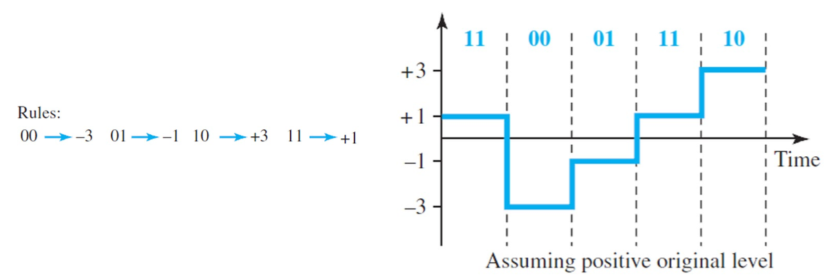
Multilevel Schemes: 2B1Q
- Two binary, one quaternary (2B1Q), uses data patterns of size 2 and encodes the 2-bit patterns as one signal element belonging to a four-level signal.
- The 2B1Q scheme is used in DSL (Digital Subscriber line) technology to provide a high-speed connection to the Internet by using subscriber telephone lines.
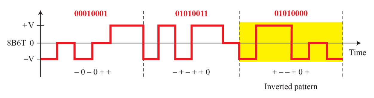
Multilevel Schemes: 8B6T
- Eight binary, six ternary (8B6T).
- Used with 100BASE-4T cable
- 3^6 - 2^8 = 473 redundant signal elements that provide synchronization, error detection, and DC balance
- Each signal pattern has a weight of 0 or +1 DC values.
Multilevel: 8B6T
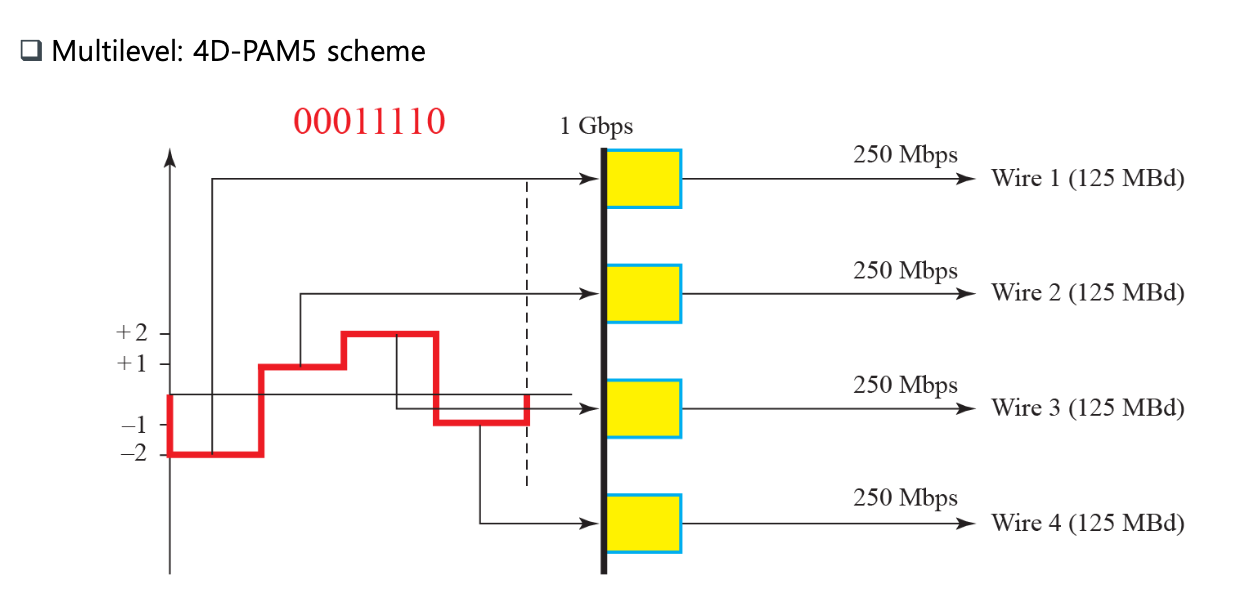
Multilevel Schemes: 4D-PAM5
- Four-dimensional five level pulse amplitude modulation (4D-PAM5)
- The 4D means that data is sent over four wires at the same time.
- It uses five voltage levels, such as -2, -1, 0, 1, and 2.
- 0 for FEC
- Similar to 8B4Q.
- An 8-bit word is translated to a signal element of four different levels.
- Gigabit LANs use this technique to send 1-Gbps data over four copper cables that can handle 125 Mbaud
Multilevel: 4D-PAM5 scheme
Block Coding
-
We need redundancy to ensure synchronization and to provide some kind of inherent error detecting.
-
Block coding can give us this redundancy and improve the performance of line coding.
-
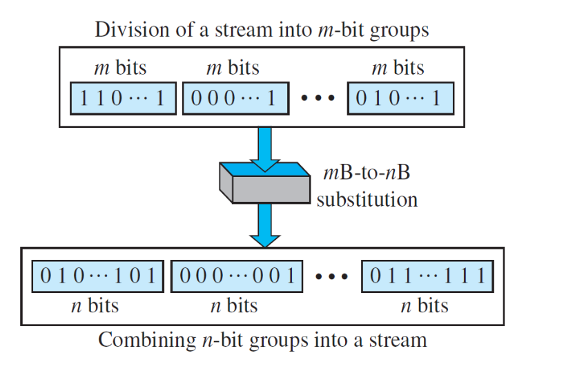
In general, block coding changes a block of m bits into a block of n bits, where n is larger than m.
-
Block coding is normally referred to as mB/nB coding.
- It replaces each m-bit group with an n-bit group.
4B/5B
- The four binary/five binary (4B/5B) coding scheme was designed to be used in combination with NRZ-I.
- A long sequence of 0s can make the receiver clock lose synchronization.
- One solution is to change the bit stream, prior to encoding with NRZ-I, so that it does not have a long stream of 0s.
- The block-coded stream does not have more than three consecutive 0s.
- In 4B/5B, the 5-bit output that replaces the 4-bit input has no more than one leading zero (left bit) and no more than two trailing zeros (right bits)
- Never more than three consecutive 0s
- Some of unused groups are used for control purposes; the others are not used at all
Substitution in 4B/5B block coding
- The redundant bits add 20 percent more baud.
- Still, the result is less than the biphase scheme which has a signal rate of 2 times that of NRZ-I.
- Not solve the DC component problem of NRZ-I. If a DC component is unacceptable, we need to use biphase or bipolar encoding.
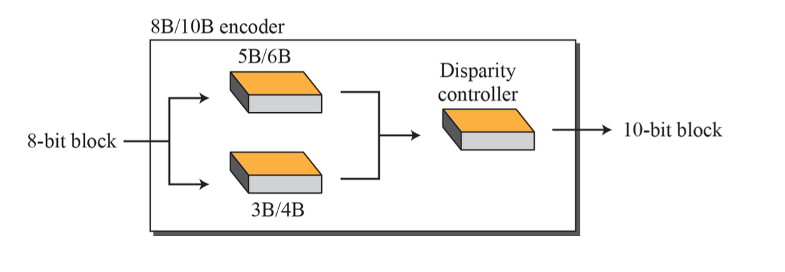
8B/10B
- Eight binary/ten binary (8B/10B) encoding
- Greater error detection capability than 4B/5B.
- The 8B/10B block coding is actually a combination of 5B/6B and 3B/4B encoding
- The split is done to simplify the mapping table.
Scrambling
We modify line and block coding to include scrambling, as shown below
- AMI used with scrambling
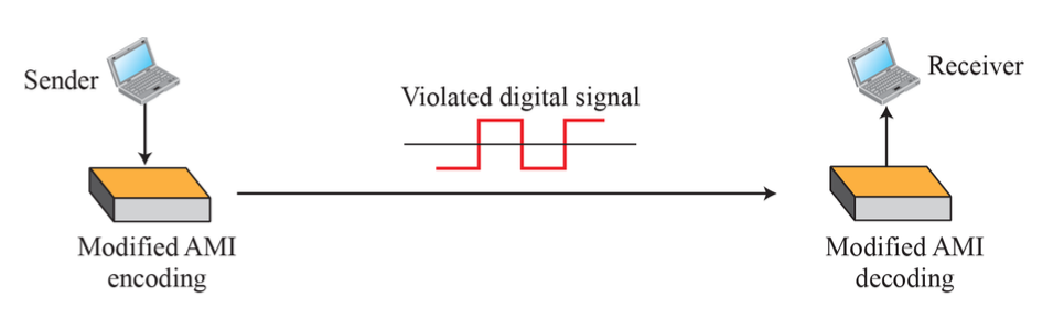
- Note that scrambling, as opposed to block coding, is done at the same time as encoding.
- The system needs to insert the required pulses based on the defined scrambling rules.
- One of common scrambling techniques is B8ZS.
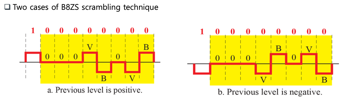
B8ZS
- Bipolar with 8-zero substitution (B8ZS)
- Eight consecutive zero-level voltages are replaced by the sequence 000VB0VB
- V: violation, B: bipolar
Transmission Mode
-
Of primary concern when we are considering the transmission of data from one device to another is the wiring, and of primary concern when we are considering the wiring is the data stream.
-
Do we send 1 bit at a time; or do we group bits into larger groups and, if so, how?
- The transmission of binary data across a link can be accomplished in either parallel or serial mode. and isochronous
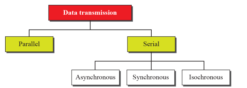
Parallel Transmission
-
Line coding is the process of converting digital data to digital signals.
-
We assume that data, in the form of text, numbers, graphical images, audio, or video, are stored in computer memory as sequences of bits.
-
Line coding converts a sequence of bits to a digital signal.
- At the sender, digital data are encoded into a digital signal
- At the receiver, the digital data are recreated by decoding the digital signal.
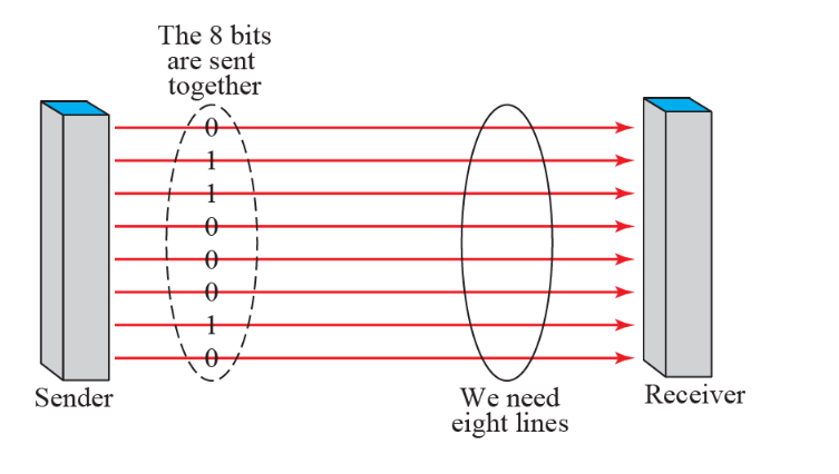
Parallel transmission
- The advantage of parallel transmission is speed.
- But, expensive
- Parallel transmission requires n communication lines (wires in the example) just to transmit the data stream
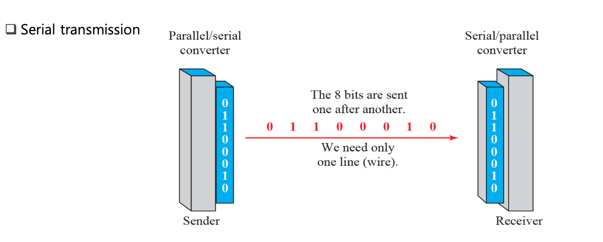
- In serial transmission one bit follows another, so we need only one communication channel rather than n to transmit data between two communicating devices
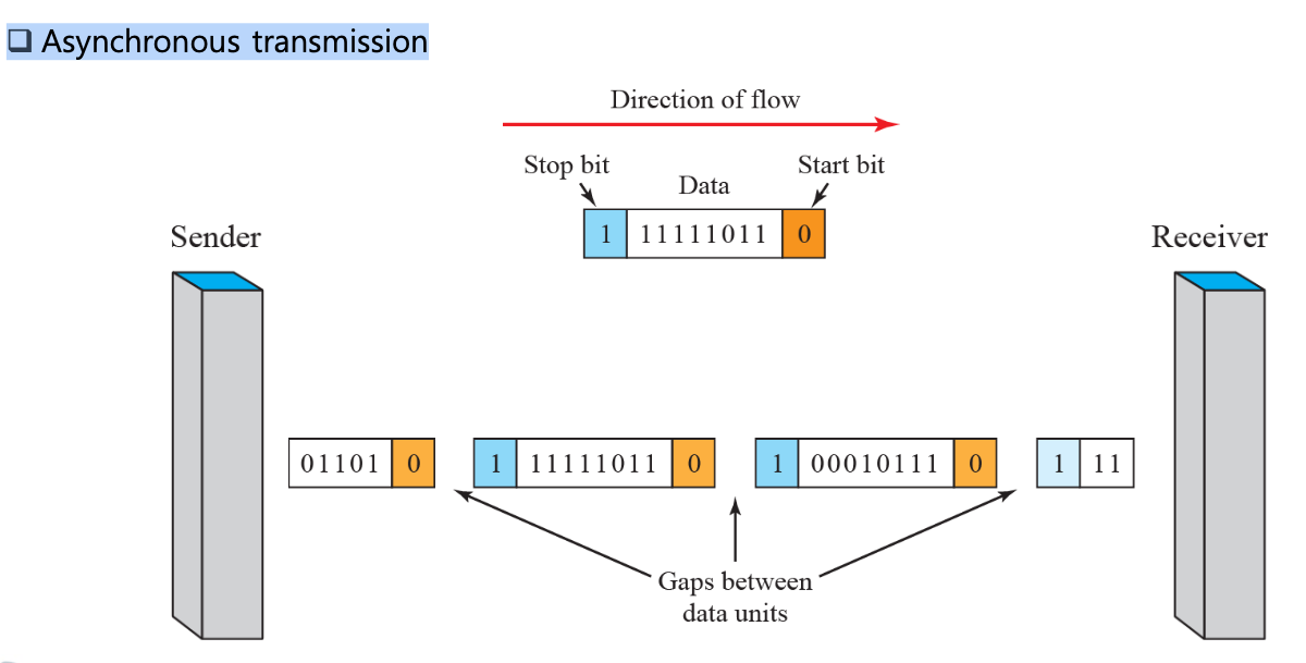
Asynchronous Transmission
- The timing of a signal is unimportant.
- Instead, information is received and translated by agreed upon patterns.
- In asynchronous transmission, we send 1 start bit(0) at the beginning and 1 or more stop bits (1s) at the end of each byte. There may be a gap between bytes.
- Asynchronous here means “asynchronous at the byte level,” but the bits are still synchronized; their durations are the same.
- Cheap and effective.
- Slower than forms of transmission that can operate without the addition of control information
- E.g., the connection of a keyboard to a computer is a natural application for asynchronous transmission.
Synchronous Transmission
- The bit stream is combined into longer “frames,” which may contain multiple bytes.
- In synchronous transmission, we send bits one after another without start or stop bits or gaps.
- It is the responsibility of the receiver to group the bits.
- The advantage of synchronous transmission is speed
- More useful for high-speed applications such as the transmission of data from one computer to another
- There may be uneven gaps between frames.
Analog-to-Digital Conversion: PCM, Delta Modulation
- We have an analog signal such as one created by a microphone or camera.
- We have seen that a digital signal is superior to an analog signal.
- The tendency today is to change an analog signal to digital data.
- Now, we describe two techniques, pulse code modulation and delta modulation.
Pulse Code Modulation (PCM)
-
The most common technique to change an analog signal to digital data (digitalization) is called pulse code modulation (PCM).
-
A PCM encoder has three processes, as shown in the next slide.
- The analog signal is sampled.
- The sampled signal is quantized.
- The quantized values are encoded as streams of bits.
